Thermostatic expansion valve is a throttling device used for flow control of refrigerant in the refrigeration system. Throttling is done to reduce the boiling point of the liquid from the condenser. this is achieved by reducing the presure of the refrigerant as it is metered through the small orifice of the throttling device. As the pressure reduces, the boiling temperature of the refrigerant also reduces.
So the main functions of a TEV is to
- To meter the liquid refrigerant from liquid into the evaporator at a rate suitable to maintain the designed operating pressure at different load condition.
- To mainatain the difference of pressure between high and low pressure side of the refrigerant.
- to amintain a constant degree of superheat at the outlet of evaporator.
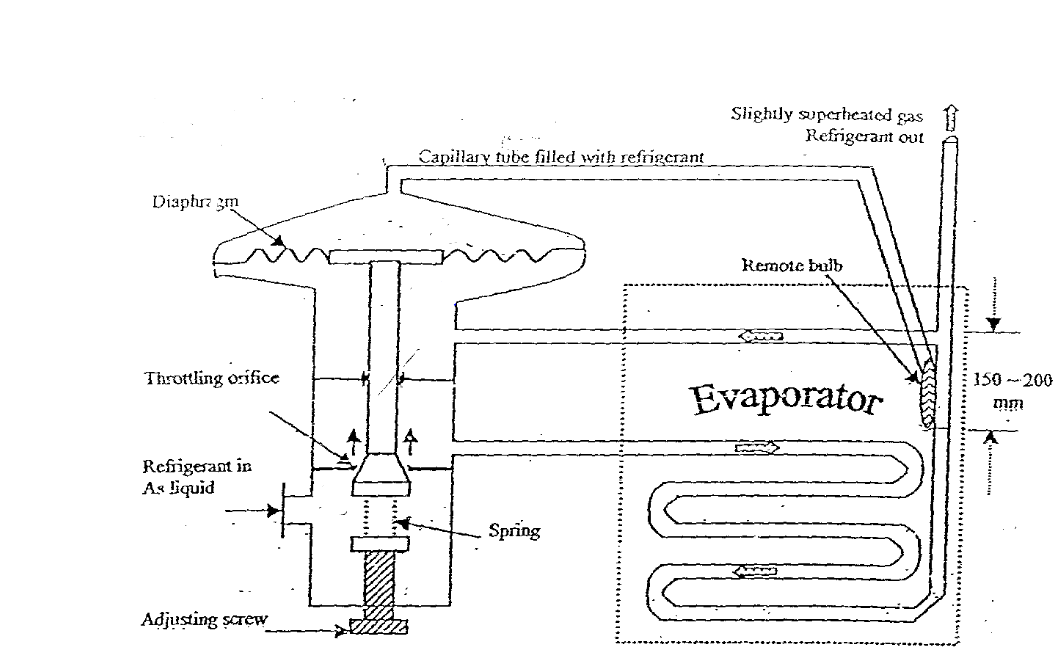
Systems using thermostatic expansion valves use basically one of two types of valves: internally equalized and externally equalized. The two types of expansion valves are similar, but not interchangeable, both types of expansion valves are Installed in the system to lower the pressure before the refrigerant enters the evaporator. The reduction in pressure is accomplished simply by passing the refrigerant through a small hole (orifice), but the opening and closing of the orifice must be controlled to compensate for changes in pressure and temperature, the temperature of refrigerant leaving the evaporator is sensed by a thermal bulb and capillary tube which moves the valve seat via a diaphragm and actuating pins. Internally equalized expansion valves permit refrigerant pressure from the outlet side of the orifice to pass through an internal passage and push against the underside of the diaphragm.Externally equalized expansion valves have a line connected to the outlet side of the evaporator and refrigerant pressure passes through this line to push against the underside of the diaphragm
Three forces which govern the thermal expansion valve’s operation are
1) The power element and remote bulb pressure (P1)
2) the evaporator pressure (P2), and
3) the superheat spring equivalent pressure (P3).
We will deal with both types of TEV, 1) Internally equalized TEV 2) Externally Equalized TEV
1) Internal Equalized Expansion Valve
(Eventhough R12 is banned as per the montreal protocal, we have used R12 refigerant for the purpose of calculation)
Three conditions present themselves in the operation of this valve: first, the balanced forces; second, an increase in superheat; third, a decrease in superheat. The remote bulb and the power element make up a closed system (power assembly), and in the following discussion, it is assumed that the remote bulb and power element are charged with the same refrigerant as that in the system. The remote bulb and Power element pressure which corresponds to the saturation pressure of the refrigerant gas temperature leaving the evaporator, moves the valve pin in the opening direction.
Opposed to this opening force on the underneath side of the diaphragm and acting in the closing direction are two forces: (1) the force exerted by the evaporator pressure and (2) that exerted by the superheat spring. In the first condition, the valve will assume a stable control position when these three Forces are in balance (that is, when P1 = P2 + P3). In the next step, the temperature of the refrigerant gas at the evaporator outlet (remote bulb location) increases above the saturation temperature corresponding to the evaporator pressure as it becomes superheated. The pressure thus generated in the remote bulb, due to this higher temperature, Increases above the combined pressures of the evaporator pressure and the superheat spring (P1 greater than P2 + P3) And causes the valve pin to move in an opening direction. Conversely, as the temperature of the refrigerant gas leaving the evaporator decreases, the pressure in the remote bulb and Power assembly also decreases and the combine evaporator and Spring pressure cause the valve pin to move in a closing Direction (P1 less than P2 + P3).
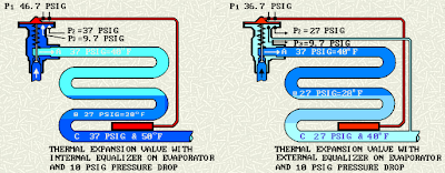
For example, when the evaporator is operating with R12 at a Temperature of 40EF or a pressure of 37 Psig and the refrigerant gas leaving the evaporator at the remote bulb Location is 50EF a condition of 10EF superheat exists.
Since the remote bulb and power assembly are charged with the same refrigerant as that used in the system (R12), its Pressure (P1) will follow its saturation pressure temperature characteristics. With the liquid in the remote bulb at 50ºF the pressure inside the remote bulb and power assembly will be 46.7 Psig acting in an opening direction.
Beneath the diaphragm and action a closing direction is the evaporator pressure (P2) of 37 Psig and the spring pressure (P3) for a 10EF superheat setting of 9.7 Psig (37 + 9.7 = 46.7) making A total of 46.7 Psig. The valve is in balance, 46.7 Psig Above the diaphragm and 46.7 Psig below the diaphragm. changes in load, increasing the superheat, will cause the thermal expansion valve pin to move in an opening direction. Conversely, a change, decreasing the superheat, will cause the thermal valve pin to move in a closing direction.

2)External Equalized Expansion Valve
When the pressure drop through the evaporator is of any consequence, i.e., in general a pressure drop equivalent to 3 degrees in the air-conditioning range, 2 degrees in the commercial temperature range, and 1 degree in the low temperature range, it will hold the thermal expansion valve in a relatively "restricted" position and reduce the system capacity, unless a thermal expansion valve with an external equalizer is used. The evaporator should be selected for the operating conditions and the thermal expansion valve selected and applied accordingly.
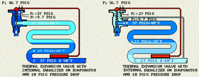
For example, an evaporator is fed by a thermal expansion valve with an internal equalizer, where a sizeable pressure drop of 10 Psig is present. The pressure at point "c" is 27 Psig or 10 Psig lower than at the valve outlet, point "a"; however, the pressure of 37 Psig at point "a" is the pressure acting on the lower side of the diaphragm in a closing Direction. With the valve spring set at a compression equivalent to 10EF superheat or a pressure of 9.7 Psig, the required pressure above the diaphragm to equalize the forces is (37 + 9.7) or 46.7 Psig. This pressure corresponds to a saturation temperature of 50EF. It is evident that the refrigerant temperature at point "c" must be 50EF if the valve is to be in equilibrium. Since the pressure at this point is only 27 Psig and the corresponding saturation temperature is 28EF a superheat of 50EF - 28EF or 22 Degrees is required to open the valve. This increase in superheat, from 10 to 22 degrees make it necessary to use more of the evaporator surface to produce this higher superheated refrigerant gas. Therefore, the amount of evaporator surface available for absorption of latent heat of vaporization of the refrigerant is reduced; the evaporator is starved before the required superheat is reached. Since the pressure drop across the evaporator, which caused this high superheat condition, increases with the load because of friction, this "restriction" or "starving" effect is increased when the demand on the thermal valve capacity is greatest.
In order to compensate for an excessive pressure drop through an evaporator, the thermal expansion valve must be of the external equalizer type, with the equalizer line connected either into the evaporator at a point beyond the greatest pressure drop or into the suction line at a point on the compressor side of the remote bulb location.
In general and as a rule of thumb, the equalizer line should be connected to the suction line at the evaporator outlet. If the external equalizer type of thermal expansion valve is used, with the equalizer line connected to the suction line, the true evaporator outlet pressure is exerted beneath the thermal valve diaphragm, the operating pressures on the valve diaphragm are now free from any effect of the pressure drop through the evaporator, and the thermal valve will respond to the superheat of the refrigerant gas leaving the evaporator.
When the same conditions of pressure drop exists in a system with a thermal expansion valve which has the external equalizer feature, the same pressure drop still exists through the evaporator; however, the pressure under the diaphragm is now the same as the pressure at the end of the evaporator, point "c", or 27 Psig.
The required pressure above the diaphragm for equilibrium is 27 + 9.7 or 36 Psig. This pressure, 36.7 Psig, corresponds to a saturation temperature of 40EF and the superheat required is now (40EF - 28EF) 12 degrees. The use of an external equalizer has reduced the superheat from 22 to 12 degrees. Thus, the capacity of a system, having an evaporator with a sizable pressure drop, will be increased by the use of a thermal expansion valve with the external equalizer as compared to the use of an internally equalized valve. As pointed out Earlier the external equalizer line must be installed beyond the point of greatest pressure drop.
So external equalizing line is used when there is a marginal pressure drop inside the evaporator, so we can avoid starvation of refrigerant
So the main functions of a TEV is to
- To meter the liquid refrigerant from liquid into the evaporator at a rate suitable to maintain the designed operating pressure at different load condition.
- To mainatain the difference of pressure between high and low pressure side of the refrigerant.
- to amintain a constant degree of superheat at the outlet of evaporator.
Systems using thermostatic expansion valves use basically one of two types of valves: internally equalized and externally equalized. The two types of expansion valves are similar, but not interchangeable, both types of expansion valves are Installed in the system to lower the pressure before the refrigerant enters the evaporator. The reduction in pressure is accomplished simply by passing the refrigerant through a small hole (orifice), but the opening and closing of the orifice must be controlled to compensate for changes in pressure and temperature, the temperature of refrigerant leaving the evaporator is sensed by a thermal bulb and capillary tube which moves the valve seat via a diaphragm and actuating pins. Internally equalized expansion valves permit refrigerant pressure from the outlet side of the orifice to pass through an internal passage and push against the underside of the diaphragm.Externally equalized expansion valves have a line connected to the outlet side of the evaporator and refrigerant pressure passes through this line to push against the underside of the diaphragm
 |
| Internal Equalizing TEV |
 |
| External Equalizing TEV |
Three forces which govern the thermal expansion valve’s operation are
1) The power element and remote bulb pressure (P1)
2) the evaporator pressure (P2), and
3) the superheat spring equivalent pressure (P3).
We will deal with both types of TEV, 1) Internally equalized TEV 2) Externally Equalized TEV
1) Internal Equalized Expansion Valve
(Eventhough R12 is banned as per the montreal protocal, we have used R12 refigerant for the purpose of calculation)
Three conditions present themselves in the operation of this valve: first, the balanced forces; second, an increase in superheat; third, a decrease in superheat. The remote bulb and the power element make up a closed system (power assembly), and in the following discussion, it is assumed that the remote bulb and power element are charged with the same refrigerant as that in the system. The remote bulb and Power element pressure which corresponds to the saturation pressure of the refrigerant gas temperature leaving the evaporator, moves the valve pin in the opening direction.
Opposed to this opening force on the underneath side of the diaphragm and acting in the closing direction are two forces: (1) the force exerted by the evaporator pressure and (2) that exerted by the superheat spring. In the first condition, the valve will assume a stable control position when these three Forces are in balance (that is, when P1 = P2 + P3). In the next step, the temperature of the refrigerant gas at the evaporator outlet (remote bulb location) increases above the saturation temperature corresponding to the evaporator pressure as it becomes superheated. The pressure thus generated in the remote bulb, due to this higher temperature, Increases above the combined pressures of the evaporator pressure and the superheat spring (P1 greater than P2 + P3) And causes the valve pin to move in an opening direction. Conversely, as the temperature of the refrigerant gas leaving the evaporator decreases, the pressure in the remote bulb and Power assembly also decreases and the combine evaporator and Spring pressure cause the valve pin to move in a closing Direction (P1 less than P2 + P3).
For example, when the evaporator is operating with R12 at a Temperature of 40EF or a pressure of 37 Psig and the refrigerant gas leaving the evaporator at the remote bulb Location is 50EF a condition of 10EF superheat exists.
Since the remote bulb and power assembly are charged with the same refrigerant as that used in the system (R12), its Pressure (P1) will follow its saturation pressure temperature characteristics. With the liquid in the remote bulb at 50ºF the pressure inside the remote bulb and power assembly will be 46.7 Psig acting in an opening direction.
Beneath the diaphragm and action a closing direction is the evaporator pressure (P2) of 37 Psig and the spring pressure (P3) for a 10EF superheat setting of 9.7 Psig (37 + 9.7 = 46.7) making A total of 46.7 Psig. The valve is in balance, 46.7 Psig Above the diaphragm and 46.7 Psig below the diaphragm. changes in load, increasing the superheat, will cause the thermal expansion valve pin to move in an opening direction. Conversely, a change, decreasing the superheat, will cause the thermal valve pin to move in a closing direction.

2)External Equalized Expansion Valve
When the pressure drop through the evaporator is of any consequence, i.e., in general a pressure drop equivalent to 3 degrees in the air-conditioning range, 2 degrees in the commercial temperature range, and 1 degree in the low temperature range, it will hold the thermal expansion valve in a relatively "restricted" position and reduce the system capacity, unless a thermal expansion valve with an external equalizer is used. The evaporator should be selected for the operating conditions and the thermal expansion valve selected and applied accordingly.
For example, an evaporator is fed by a thermal expansion valve with an internal equalizer, where a sizeable pressure drop of 10 Psig is present. The pressure at point "c" is 27 Psig or 10 Psig lower than at the valve outlet, point "a"; however, the pressure of 37 Psig at point "a" is the pressure acting on the lower side of the diaphragm in a closing Direction. With the valve spring set at a compression equivalent to 10EF superheat or a pressure of 9.7 Psig, the required pressure above the diaphragm to equalize the forces is (37 + 9.7) or 46.7 Psig. This pressure corresponds to a saturation temperature of 50EF. It is evident that the refrigerant temperature at point "c" must be 50EF if the valve is to be in equilibrium. Since the pressure at this point is only 27 Psig and the corresponding saturation temperature is 28EF a superheat of 50EF - 28EF or 22 Degrees is required to open the valve. This increase in superheat, from 10 to 22 degrees make it necessary to use more of the evaporator surface to produce this higher superheated refrigerant gas. Therefore, the amount of evaporator surface available for absorption of latent heat of vaporization of the refrigerant is reduced; the evaporator is starved before the required superheat is reached. Since the pressure drop across the evaporator, which caused this high superheat condition, increases with the load because of friction, this "restriction" or "starving" effect is increased when the demand on the thermal valve capacity is greatest.
In order to compensate for an excessive pressure drop through an evaporator, the thermal expansion valve must be of the external equalizer type, with the equalizer line connected either into the evaporator at a point beyond the greatest pressure drop or into the suction line at a point on the compressor side of the remote bulb location.
In general and as a rule of thumb, the equalizer line should be connected to the suction line at the evaporator outlet. If the external equalizer type of thermal expansion valve is used, with the equalizer line connected to the suction line, the true evaporator outlet pressure is exerted beneath the thermal valve diaphragm, the operating pressures on the valve diaphragm are now free from any effect of the pressure drop through the evaporator, and the thermal valve will respond to the superheat of the refrigerant gas leaving the evaporator.
When the same conditions of pressure drop exists in a system with a thermal expansion valve which has the external equalizer feature, the same pressure drop still exists through the evaporator; however, the pressure under the diaphragm is now the same as the pressure at the end of the evaporator, point "c", or 27 Psig.
The required pressure above the diaphragm for equilibrium is 27 + 9.7 or 36 Psig. This pressure, 36.7 Psig, corresponds to a saturation temperature of 40EF and the superheat required is now (40EF - 28EF) 12 degrees. The use of an external equalizer has reduced the superheat from 22 to 12 degrees. Thus, the capacity of a system, having an evaporator with a sizable pressure drop, will be increased by the use of a thermal expansion valve with the external equalizer as compared to the use of an internally equalized valve. As pointed out Earlier the external equalizer line must be installed beyond the point of greatest pressure drop.
So external equalizing line is used when there is a marginal pressure drop inside the evaporator, so we can avoid starvation of refrigerant


breaker.PNG)